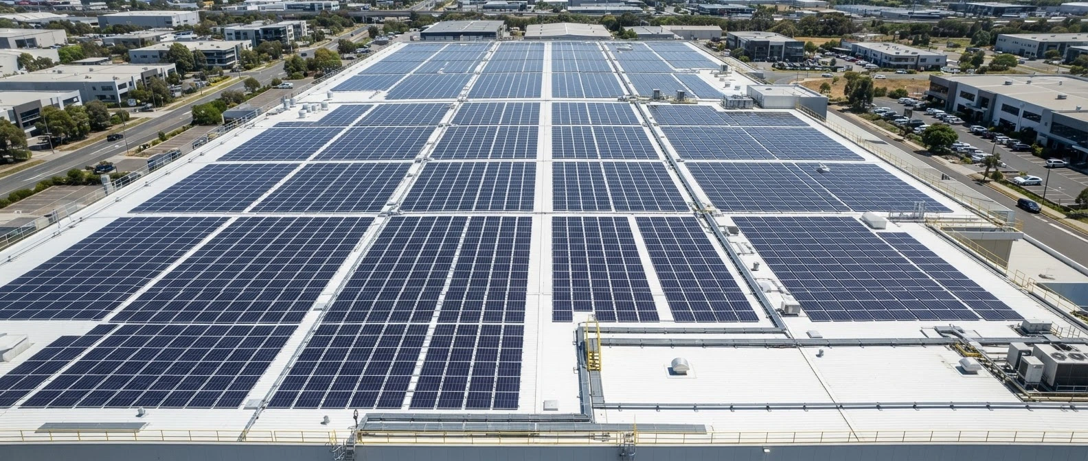
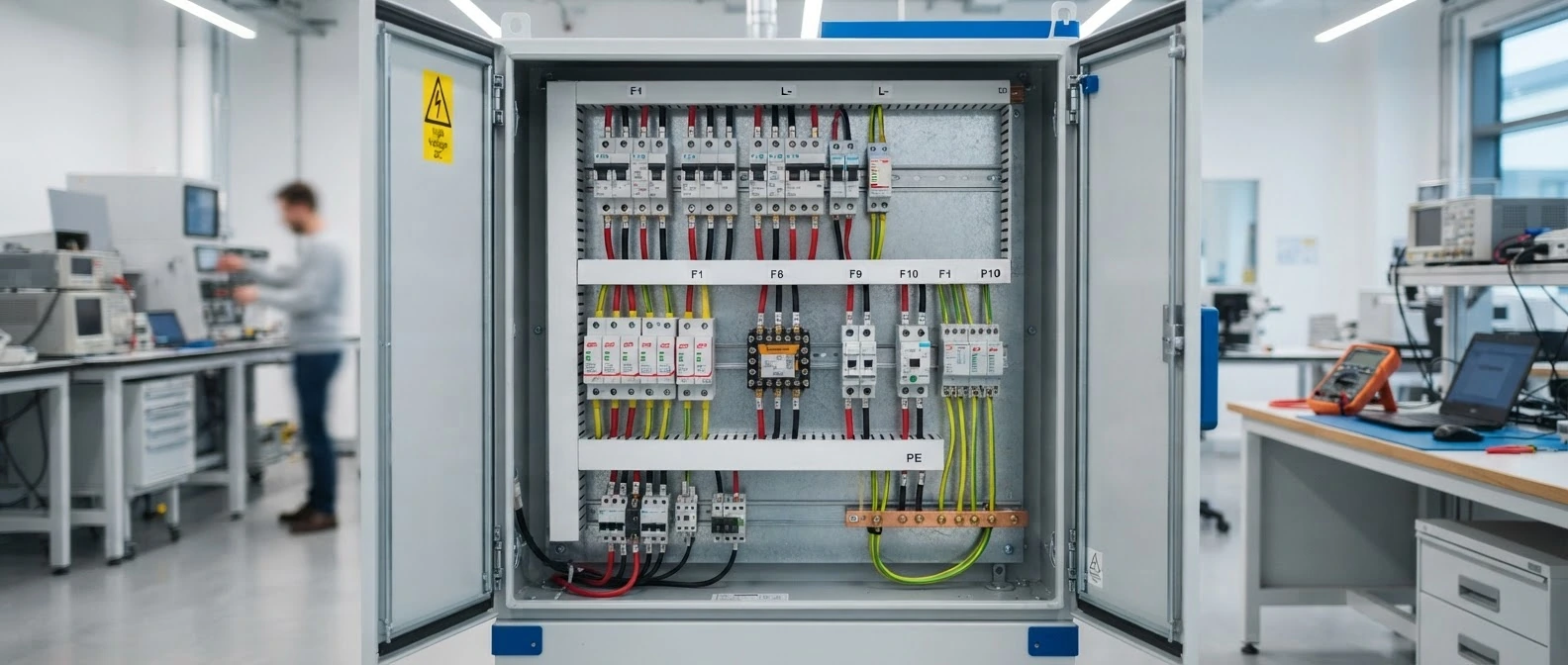
Every connection is built, tested and recorded.
Follow the energy path that commissioning verifies: strings and inverters, AC combiner and protection, the LT panel and the meter, and the communication links the EMS depends on.

Communication network
Measurements and commands travel on several networks: field buses inside equipment, a plant network to the controller, and an encrypted link for remote monitoring. Each has its own timing and failure behaviour.
- Field bus: BMS on CAN, meters and DG controller on RS-485 Modbus RTU: fast, local, deterministic.
- Plant network: PCS and inverters on Modbus TCP or IEC 61850 over Ethernet to the EMS gateway.
- Remote: An encrypted link sends data to monitoring; local control never depends on it.
- Link lost: If a device stops answering, the EMS falls back to a defined safe mode.
- What we check:
- Protocol support per device and firmware
- Network segregation and cyber-security
- Fallback modes on communication loss
Seven gates from project-ready to completion.
Documents reviewed, evidence loaded, safety boundaries defined.
Pre-construction QA and serial identities checked.
Foundations, access and protection confirmed.
Structures, modules, switchgear and storage mounted.
Loop tests, thermal imaging and isolation checks.
Monitoring and EMS parameters configured for operation.
Handover file accepted with open issues closed.
Progress measured on hardware, not schedules.
- Structure
- PV modules & strings
- DC cabling & insulation
- PCS / inverter synchronisation
- BESS safety checks
- AC protection settings
- Earthing
- Metering / EMS communications
- Testing & commissioning
Illustrative verification workflow, not a live project status.
What stays on file.
Dated visual record of electrical assembly.
Certificates and origin records where available.
Insulation resistance and thermal imaging.
Key devices mapped to their location.
Signed compliance and handover packages.
Utility documentation and commissioning support.
Single-lines, configurations and equipment documents for submission.
Load and engineering results compiled for utility applications.
Structural and isolation-test evidence.
Communication outputs matched to utility rules.
Engineers present during first power flows.
Reactive power, surge protection and isolation limits verified.
Utility approval, connection timelines and meter release depend on regional utility policy and project parameters.
Start with how your site actually uses energy.
Share a few details and your recent bills. A Samvora engineer reviews your load, tariff and reliability needs before anything is proposed.