Protection and conversion are designed, not assumed.
Two of the checks behind every design: protection that isolates only the faulted feeder in grid and island modes, and converters whose limits match the loads they will carry.
Protection and selectivity
Protection detects abnormal current and isolates only the faulted part of the system. Converter-based sources supply limited fault current, so settings are coordinated for both grid and island operation.
- Normal: Current transformers report feeder current to the relays; all breakers closed.
- Fault: A short circuit on one feeder makes current rise sharply.
- Trip: The nearest relay picks up and its breaker opens within its set time.
- Selectivity: Upstream breakers wait longer, so the rest of the site stays supplied.
- What we check:
- Fault levels from grid, DG and converters
- Relay settings for grid-connected and island modes
- Earthing system and arc-flash review
Power conversion system (PCS)
A bidirectional converter between the battery’s DC and the site’s AC. IGBT bridges switch thousands of times a second; a filter turns the pulses into a clean sine wave.
- Inverting: Battery DC is switched into pulses and filtered into AC to supply the site.
- Rectifying: The same bridge runs in reverse to charge the battery from AC.
- Grid-following: A phase-locked loop tracks the grid voltage and the PCS injects or absorbs a set current. It needs a grid (or a grid-forming source) to follow, so it stops when the grid fails.
- Grid-forming: With the grid gone, the PCS generates its own voltage and frequency reference: the site becomes an island.
- Current limit: If a load or fault asks for more than the converter can give, current is clamped to protect the IGBTs.
- What we check:
- Continuous and short-term overload rating
- Grid-forming capability and islanding certification by the manufacturer
- Efficiency curve, cooling and ambient derating
Not a checklist of boxes.
Module choice, degradation and shading logic.
Thermal limits, cycling and state-of-health behaviour.
Reactive power, synchronisation and isolation capabilities.
Trip thresholds, anti-islanding and current limits.
Breakers, fuses and cable routes drawn precisely.
Peak-shaving routines and charge/discharge rules.
Model-by-model, not brand-by-brand.
Model-specific datasheets and limits.
Firmware and interface compatibility.
Continuous and overload capability.
Controller behaviour checked together.
Equipment selection becomes engineering evidence only after model-specific validation.
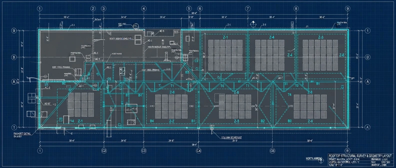
Geometry and fabrication definition.
Spatial boundaries and shading elements captured.
Accurate boundaries and load capacities.
Arrays with maintenance clearances.
Checked against applicable local codes.
Structural analysis and design checks require engineering review for each project.
Start with how your site actually uses energy.
Share a few details and your recent bills. A Samvora engineer reviews your load, tariff and reliability needs before anything is proposed.